Overview
This is a mission space simulator. The simulator is running on a server in a datacenter in Dallas, TX. The backend simulator is written in PHP and makes a good attempt to simulate running an Orange Bay. You can power up / down, home the bay and dispatch the ride just like you would do in real life. You can also hit ride stop, E-Stop, dispatch inhibit etc. and they act like you would expect. If the ride was running and you click Ride Stop the ride will return to the home position and raise the floors. If you hit E-Stop while the ride is running it will come to a fairly quick stop and the floors will be left down. If you hit power disconnect while the ride is running is will coast to a stop and the floors will be left down.
Naturally after an E-Stop or Power Down you will have to power up and re-home the bay. There is one capsule control panel to open and close all 10 capsules, of course in real life you have to do this 10 times... When the ride is finished the capsule doors and exit doors will automatically open, and after a brief time the entrance doors will open and then eventually automatically close just like in real life.
There is a random chance that you will get one or more door obstructions which will cause the entrance door LED to blink yellow, you must then manually close the entrance doors. In real life you would walk the perimeter inside the bay when this happens. After closing the capsules and all entrance, ADA, and exit doors and if there are no dispatch inhibits, ride stops, or e-stops you should get the flashing green dispatch button.
Once you press the dispatch button there is a random chance that you may get one or more intelli-video or motion sensor alarms. You will need to open your exit doors to investigate the issue and then ask mission control to clear your dispatch inhibit. Once cleared you should be able to dispatch the ride. In the simulator it will not give you an alarm twice in a row (so no need to retrain!).
The web portion of the simulator is a combination of html, css, and a lot of javascript. Every attempt was made to make this simulator as accurate as possible but is not meant to be a replacement for live instructor training. Also it is a shared web page, if you are interacting with it and you suddenly see a ride stop it may be that another person has logged in and clicked ride stop! When you open the web page it will ask you for a 4 digit code to proceed. It's the same code we use on our devices. I hope you enjoy the simulator. From time to time I host Bay 5 pizza parties at my house where you can play around with the physical Bay 5 simulator panels and even use the intercom!
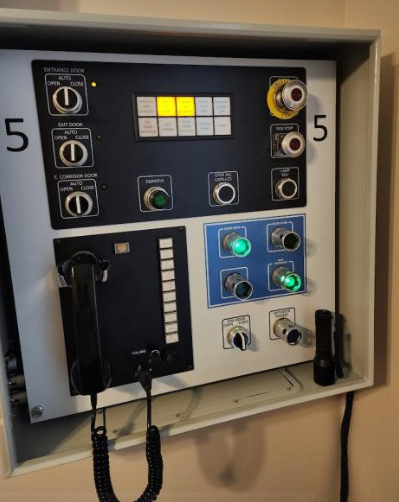
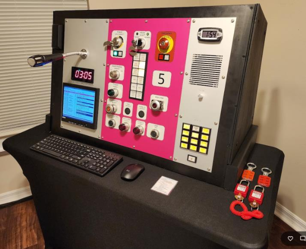
Hardware Construction
The physical Bay 5 was about a 6 month effort in sourcing the physical buttons, switches, indicators etc to match the actual panels for the real ride as well as assembling, soldering, and crimping everything together. I went through several revisions along the way especially with the wiring between the two panels and how I drive the 24V LEDs.
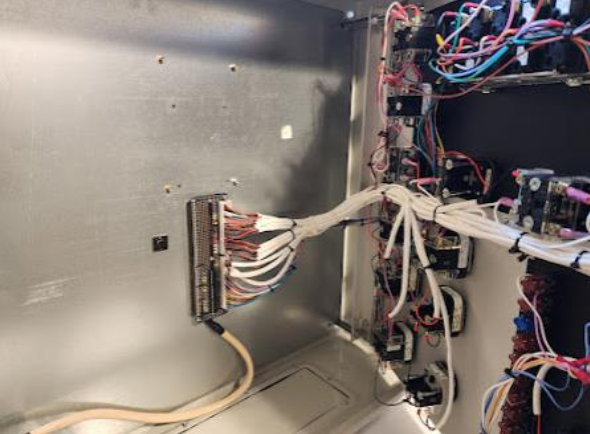
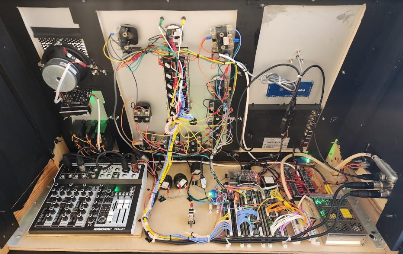
Most of the hardware switches and indicators were purchased used on E-Bay but some I had to purchase new from the suppliers. The panels were cutout and manufactured by a company called Front Panel Express. I used their free design tool to design each panel specifying the exact size and location of any cutouts and any printed graphics or engraved lettering.
The panel itself is run by a Rasberry Pi linux computer and uses an I2C (2-wire data bus) to send and receive data to 6 separate 16 GPIO daughter boards (these give 16 general purpose I/O pins each) that I use to detect switches and control panel indicators. The 12C bus also sends data to the countdown LED timer. The hdmi output from the raspberry pi is connected to the VDT and basically is displaying a web page that shows the VDT or BAY overhead view. There are also two relays, one to mute / unmute the mission control microphone based on the intercom toggle switch and another for the power disconnect which removes the 24v power from the panels.
Whenever you press a physical button on the panel it sends an http request to the server in Dallas running the simulator much like when you interact with the web based simulator. There is a power supply which provides 24v (for the LED indicators), 5v (for logic boards and the raspberry Pi), and 12v for the intercom amplifiers. There is also a small mixing board that handles the intercom audio and gives a good side tone mix for the handset in the launch panel.
There are buzzers for the alarm and intercom paging as well. I also use an Arduino nano to control the alarm on / off cadence and intercom paging beep duration. The code on the raspberry pi is a mixture of Python (to send and receive data from the I2C bus), and php to send and receive data to the backend simulator in Dallas and the web browser to display the VDT.
Launch Panel
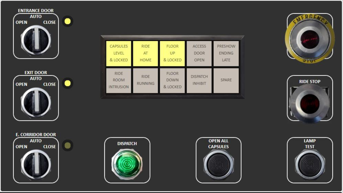
- Entrance/Exit / Exit Corridor Doors: Mouse down on the left side of the Knob to open, the right side is for close. The switch springs back to the auto position just like in real life. If you have the BAY view showing you can see the doors opening and closing! Doors take 5 seconds to fully open or close. When cycling exit doors either watch that the doors are fully opened before closing or wait just over 5 seconds before closing.
- E-Stop: You can push it in and click on the rim to pull it back out. As in real life you will have to power cycle and re-home the bay after an E-Stop.
- Ride Stop: Press once to engage, Press a second time in the middle to lower the RMP lockout guard. If the guard is lowered you have to press again in the center to raise the guard. To clear the ride stop lift up on the knob by clicking the outer rim.
Note: The Ride stop will then flash and you will have to go to mission control to clear it just like in real life. - Dispatch Button: Once the entrance doors, ADA door, and exit doors are shut and the capsules are level and locked and if you have no E-Stop or Ride Stop then the dispatch button will blink green. Simply press it to launch the ride. It's fun to have the BAY showing when you do this. You will see the indicator lights change just like in real life. Also the VDT will update with Ride Run Start and Done messages etc. Have FUN!
- Open all capsules: Click this button to open all the capsules. Floors must be up and exit doors opened for this to function.
- Lamp Test: Press and hold to turn on all indicator lights.
VDT (Video Display Terminal)
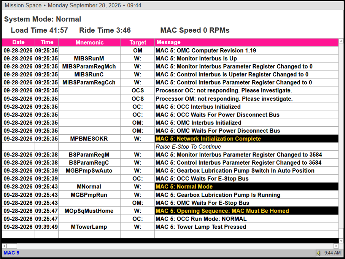
This shows the VDT screen much like you would see in real life. Most messages are pretty accurate as to what you would actually see in real life. Naturally not every message will be exact especially during power up / down, but it pretty much follows what you would see. Currently the System Mode: will always show NORMAL even during power down / up. One day I'll fix that. The Load Time, Run Time, and MAC Speed are pretty accurate.
Mission Control Panel
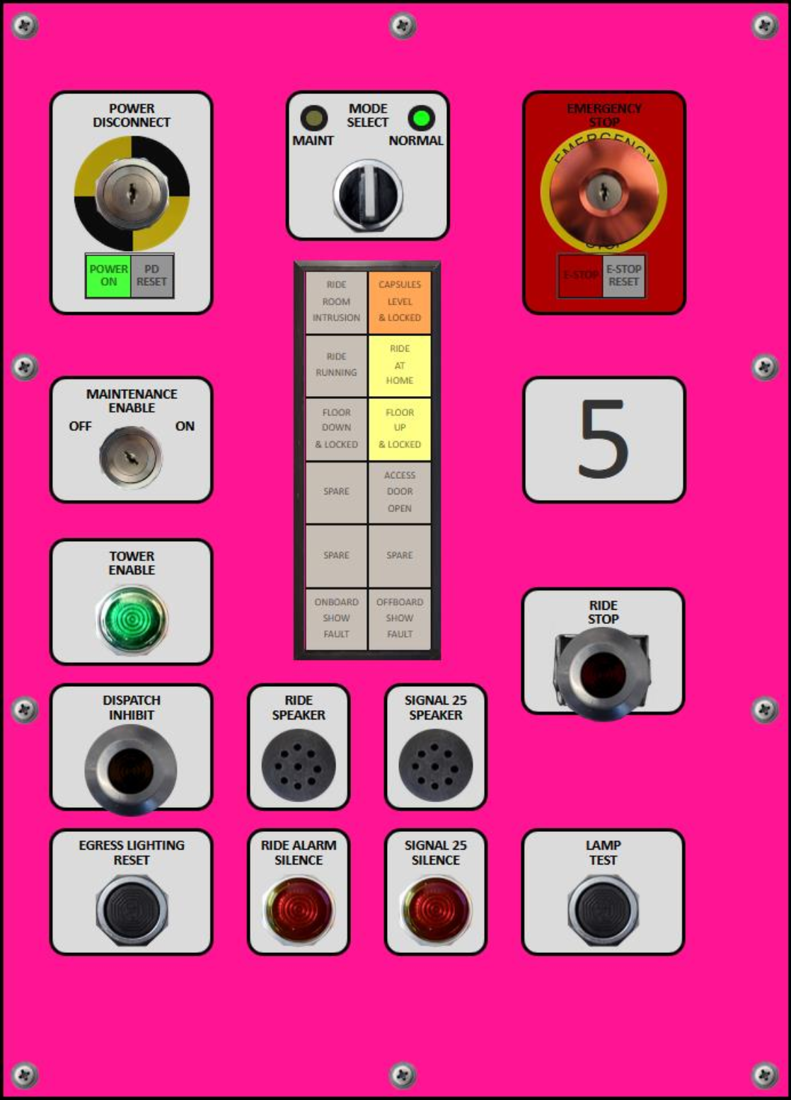
- Power Disconnect: Push in the middle to disconnect power (watch for Register Changed to 3584 before powering back on), if the ride is running it will coast to a stop and floors will be left down. When powered off simply click again to power up the ride again.
- E-Stop: Press once to engage. If the ride is running it will come to a stop by applying the breaks, floors will be left in the down position. The ride will need to be power cycled and homed. After power cycling look for 'Raise E-Stop To Continue' on the VDT, if you see 'Press E-Stop To Continue' then you will need to press it and raise it. NOTE: If you powered down before engaging E-Stop you will get the 'Press E-Stop To Continue'. Both E-Stop buttons in Launch Director panel and Mission Control will need to be raised before you get the dancing lights.
- PD RESET: This white indicator will flash once you raise the E-Stop after powering up the ride. Simply click the PD RESET to continue the power up sequence.
- MODE SELECT: After clicking PD RESET during power up the MODE SELECT will alternate flashing between Yellow (MAINT) and Green (NORMAL) Select NORMAL by pressing the right side (rotate right) of the MODE SELECT knob.
- E-STOP RESET: When flashing yellow press it to finish the power up dancing light sequence. You should see Opening Sequence: MAC Must Be Homed and OCC Run Mode: NORMAL. Now wait for Launch Director to ask for Tower Enable.
- Maintenance Enable: This switch is not used in the simulator. In real life if powering up in maintenance mode the maintenance staff will instruct you when to set this key switch to the ON position to enable the maintenance panel in the bay.
- Tower Enable: During Homing the Launch Director will call Mission Control to ask for a Tower Enable (the button will be flashing green). Launch Director must press the green Dispatch button and Mission Control must press the green Tower Enable within 4 seconds to start the homing procedure. In the web based simulator first press on the Tower Enable button in Mission Control then within 4 seconds press the Dispatch button in the Launch Director panel to start the homing procedure. During homing the floors will cycle and the bay if necessary will rotate to the home position. Naturally Launch Director must first close the entrance doors, close capsule doors and cycle the exit doors before the tower enable will flash green. There can be no dispatch inhibit, ride stop, ADA door open, or E-Stop to home the bay. Once the homing is complete the Dispatch button will flash green and can be pressed to begin the first test spin of the ride.
- Dispatch Inhibit: Push in the middle to engage, click the outer ring to raise it. When flashing (clearable) click the outer ring to pull it out / spring back to clear the dispatch inhibit.
- Ride Stop: Press once to engage, Press a second time in the middle to lower the RMP lockout guard. If the guard is lowered you have to press again in the center to raise the guard. When the ride stop is enaged click the outer ring to raise it. When flashing (clearable) click the outer ring again to pull it out / spring back to clear the ride stop.
- Egress Lighting Reset: In the web based simulator this button is unused, however it does toggle the Bay 5 simulator VDT to toggle between VDT and overhead BAY view. The web based simulator always has separate VDT and overhead BAY view shown at all times.
- Ride Alarm Silence: Mission control will beep just like in real life if there is a ride stop or E-Stop alarm. Press this button to silence the alarm.
Note: Most web browsers will not play audio automatically unless you interact with the page, so pressing the lamp test is a good way to interact with the browser so you will hear the alarm beeping. - Signal 25 Silence: There are no Signal 25 alarms in the simulator, this button is for show only. It will however light up during lamp test.
- Lamp Test: Press this to test all indicator lights.
Overhead BAY View
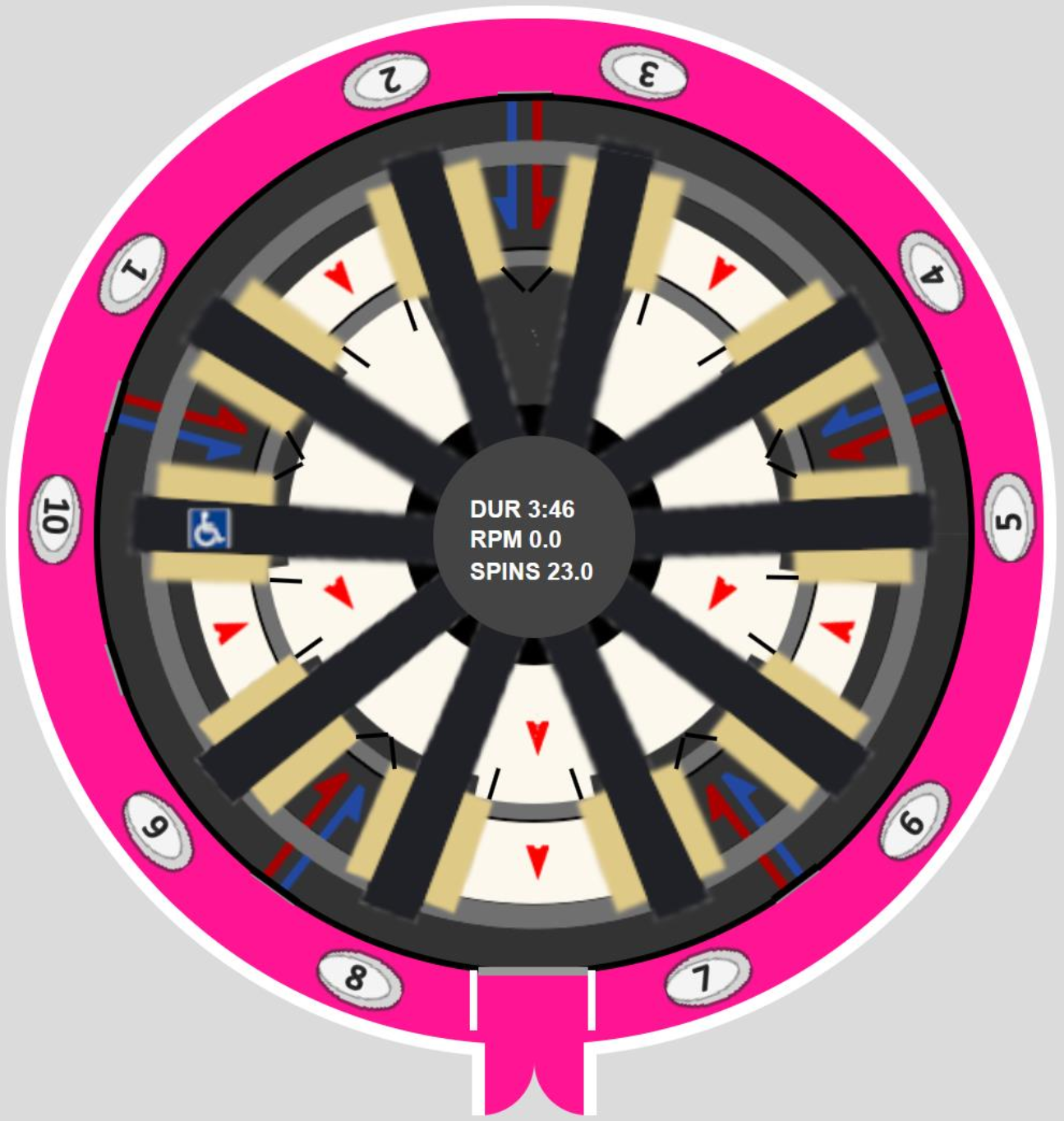
This shows the status of the simulator. You can see capsule doors, entrance, exit, and exit corridor doors. You can also see the status of the floors as they will appear darkened when lowered. You can also see the ride run time, current RPMs and total number of spins as the ride progresses.
Capsule Controls, ADA Door and Operator Present
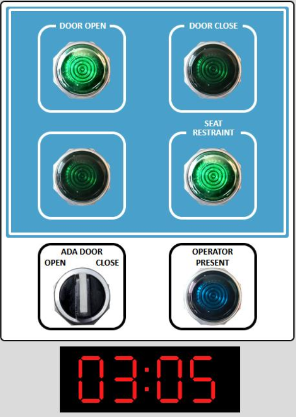
- Shift Button: In real life you need to press and hold the bottom left shift button to enable the other buttons to work. In the web simulator you do not have to hold this button down while clicking the other buttons.
- Door Open: Press to open capsule doors. Will be lit green when capsules are fully opened. Capsule doors cannot be opened or closed if the exit doors are closed or the bay is not homed.
- Door Close: Press to close capsule doors. Will be lit green when capsules are fully closed. Capsule doors cannot be opened or closed if the exit doors are closed or the bay is not homed.
- Seat Restraint: Press to release the restraints. When illuminated the restraints are locked.
- ADA Door: Press on the left of the knob (rotate left) to Open, press on the right of the knob (rotate right) to close.
- Operator Present: When flashing press to acknowledge the ready room.
- Team Dispatch Clock: This shows the ready room clock as seen if you were standing in team dispatch.